From Hentschel
(→Design Rev 2.0) |
(→Design Rev. 3.0) |
||
| (34 intermediate revisions by the same user not shown) | |||
| Line 44: | Line 44: | ||
* Inspired from [http://frederickvandenbosch.be/?p=1365 here]: | * Inspired from [http://frederickvandenbosch.be/?p=1365 here]: | ||
[[File:raspi0-box.jpg|400px]]<br clear=both> | [[File:raspi0-box.jpg|400px]]<br clear=both> | ||
| + | === Hardware === | ||
| + | ==== OLED color display based on SD1331 ==== | ||
* the Oled display which will fit into decora blank [https://www.adafruit.com/products/684 at this link] | * the Oled display which will fit into decora blank [https://www.adafruit.com/products/684 at this link] | ||
* programming the display https://media.readthedocs.org/pdf/luma-oled/latest/luma-oled.pdf | * programming the display https://media.readthedocs.org/pdf/luma-oled/latest/luma-oled.pdf | ||
| − | [[File:lcds___displays_684_LRG.jpg|400px|thumb|left]]<br clear=both> | + | [[File:lcds___displays_684_LRG.jpg|400px|thumb|left]] |
| + | <br clear=both> | ||
| + | [[Image:rpi-oled-connections_bb.png|thumb|700px|right]] | ||
* Rudimentary bit-banging Python driver: [https://gist.github.com/HentschelT/5fa11f13832cca6e7408886f4e89d05e Gist at Github] | * Rudimentary bit-banging Python driver: [https://gist.github.com/HentschelT/5fa11f13832cca6e7408886f4e89d05e Gist at Github] | ||
* Native driver package [https://github.com/rm-hull/luma.oled at Github] | * Native driver package [https://github.com/rm-hull/luma.oled at Github] | ||
| − | * | + | ** Connect display ground to Raspberry Pi ground (black wire). |
| − | [[ | + | ** Connect display VIN to Raspberry Pi 3.3 volt (red wire). |
| − | [[File: | + | ** Connect display CS to Raspberry Pi CE0 (yellow wire). |
| + | ** Connect display RST to Raspberry Pi GPIO 24 (blue wire). You can alternatively use any free digital GPIO pin for the reset pin. | ||
| + | ** Connect display DC to Raspberry Pi GPIO 23 (cyan wire). You can alternatively use any free digital GPIO pin for the DC pin. | ||
| + | ** Connect display CLK to Raspberry Pi SCLK (orange wire). | ||
| + | ** Connect display Data to Raspberry Pi MOSI (purple wire). | ||
| + | [[File:rpi-spi-oled-ssd1331-connect.png|500px|left]] | ||
| + | <br clear=both> | ||
| + | |||
| + | [[File:j8header-zero.png|400px|thumb|left|pi4j gpio]][[File:pi-gpio-bcm.png|400px|thumb|BCM GPIO]]<br clear=both> | ||
| + | |||
| + | ==== OLED B/W display based on SSD1306 ==== | ||
| + | * address 0x7B | ||
| + | * wiring: | ||
| + | [[File:raspberry_pi_RaspberryPi_I2C_bb.png|400px|left]]<br clear=both> | ||
| + | |||
| + | ==== Relay board ==== | ||
| + | * [[File:Schematic-0G-00004539-Mod-Relay-x1-5V.pdf]] | ||
| + | ==== Temp Sensor ==== | ||
| + | * Type DS18b20 | ||
| + | * Amazon [https://www.amazon.com/gp/product/B00KUNKR3M/ link] | ||
| + | |||
| + | === Software === | ||
| + | * install/enable luma.oled [https://luma-oled.readthedocs.io/en/latest/install.html link] + examples [https://github.com/rm-hull/luma.examples link], make sure examples run | ||
| + | * find font files 'concertone-regular.ttf' and 'fontawesome-webfont.ttf' | ||
| + | * install python oled server, use example scripts for verification | ||
| + | * update node-red from current version on RPi https://nodered.org/docs/hardware/raspberrypi | ||
| + | ** check this too -> https://timchooblog.wordpress.com/2016/06/14/configuring-the-johnny-five-robotics-library-to-work-in-node-red/ | ||
| + | * add "require:require" to the ''settings.js'' in the .node-red directory | ||
| + | * cd '.node-red' | ||
| + | * 'npm install node-red-contrib-stoptimer' | ||
| + | * 'npm install node-red-contrib-ds18b20-sensor' | ||
| + | * https://github.com/node-red/cookbook.nodered.org/wiki/How-to-backup-flows-and-related-configuration | ||
| + | * node-red flow for fireplace (rename to .js and import) [[:File:node-fireplace-js.doc|node-fireplace.js]] | ||
| + | |||
=== Enclosure === | === Enclosure === | ||
* the 3d-printable decora cover: [http://www.thingiverse.com/thing:1643841/#files at thingiverse] | * the 3d-printable decora cover: [http://www.thingiverse.com/thing:1643841/#files at thingiverse] | ||
| Line 70: | Line 107: | ||
# recessed reset button | # recessed reset button | ||
? | ? | ||
| + | |||
| + | == Design Rev. 3.0 == | ||
| + | [[Image:Sonoff-TH16.jpg|400px|thumb|right]] | ||
| + | [[Image:Sonoff-TH16-back.jpg|400px|thumb|right|backside]] | ||
| + | * Use Sonoff 16TH, install firmware found [https://github.com/arendst/Sonoff-Tasmota at this link] | ||
| + | * '''before this works, need to have emergency/offline action when network not available, otherwise nothing will shut the fireplace down if network is unavailable''' | ||
| + | * Schematic here: [[:File:Sonoff_TH10A(16A)_schmatic.pdf]] | ||
| + | * Find 5V connection for USB power supply on the board | ||
| + | ** make sure relay works | ||
| + | * Enclosure: | ||
| + | ** Either drill blank Decoray cover and 3d print a mount | ||
| + | ** Or 3d print the whole Decora cover including mount | ||
Latest revision as of 03:03, 9 March 2018
Contents
Basics
- getting nodes http://thomas:xxxxx@isy.home.hentschel.net/rest/nodes/
- get thermostat node http://thomas:xxxxx@isy.home.hentschel.net/rest/nodes/14%2023%20AC%201
- setting temp to 70F via REST http://thomas:xxxxx@isy.home.hentschel.net/rest/nodes/14%2023%20AC%201/set/CLISPH/140
Fan control off:
<node flag='0'>
  <address>14 23 AC 4</address>
  <name>Thermostat - Fan Control</name>
...
  <property id='ST' value='0' formatted='Off' uom='%/on/off'/>
</node>
Fan control on
<node flag='0'>
  <address>14 23 AC 4</address>
  <name>Thermostat - Fan Control</name>
...
  <property id='ST' value='255' formatted='On' uom='%/on/off'/>
</node>
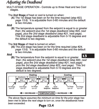
Thermostat manuals
Design
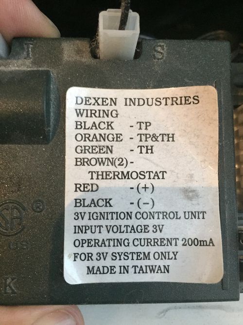
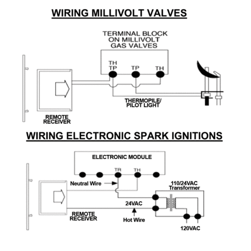
Fireplace controller - called HPC-350-M - can be found here
- Use insteon 2450 to switch fireplace low-voltage control
- Control Insteon 2450 via Thermostat - Heat Control (insteon address: 14 23 AC 3) via ISY program
- Rewire house heater to use the 2nd stage heater control on the thermostat
- Sense fire place heater via 2450 input
- Engage house heater fan via ISY program
Design Rev 2.0
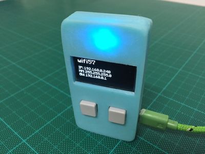
- create fireplace controller with raspberry pi zero + OLED display that fits into single gang box with decora faceplate
- Inspired from here:
Hardware
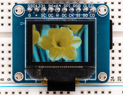
OLED color display based on SD1331
- the Oled display which will fit into decora blank at this link
- programming the display https://media.readthedocs.org/pdf/luma-oled/latest/luma-oled.pdf
- Rudimentary bit-banging Python driver: Gist at Github
- Native driver package at Github
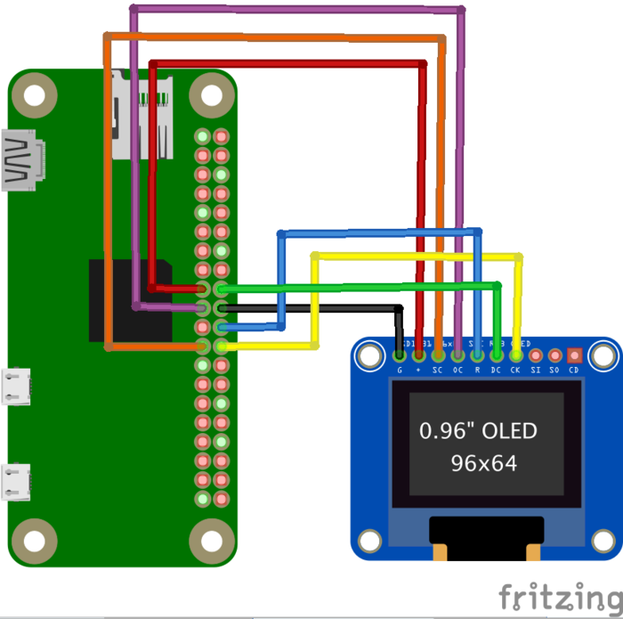
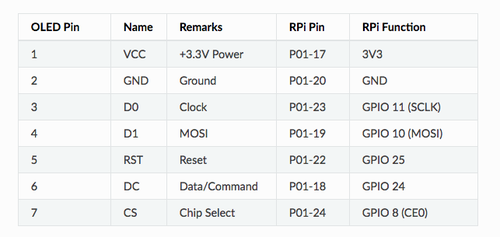
- Connect display ground to Raspberry Pi ground (black wire).
- Connect display VIN to Raspberry Pi 3.3 volt (red wire).
- Connect display CS to Raspberry Pi CE0 (yellow wire).
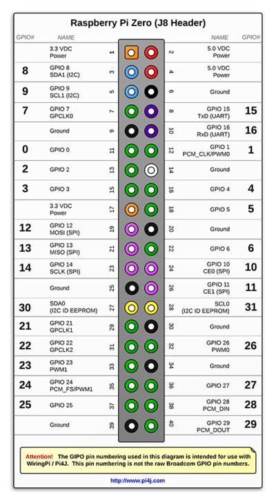
- Connect display RST to Raspberry Pi GPIO 24 (blue wire). You can alternatively use any free digital GPIO pin for the reset pin.
- Connect display DC to Raspberry Pi GPIO 23 (cyan wire). You can alternatively use any free digital GPIO pin for the DC pin.
- Connect display CLK to Raspberry Pi SCLK (orange wire).
- Connect display Data to Raspberry Pi MOSI (purple wire).
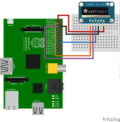
OLED B/W display based on SSD1306
- address 0x7B
- wiring:
Relay board
Temp Sensor
- Type DS18b20
- Amazon link
Software
- install/enable luma.oled link + examples link, make sure examples run
- find font files 'concertone-regular.ttf' and 'fontawesome-webfont.ttf'
- install python oled server, use example scripts for verification
- update node-red from current version on RPi https://nodered.org/docs/hardware/raspberrypi
- add "require:require" to the settings.js in the .node-red directory
- cd '.node-red'
- 'npm install node-red-contrib-stoptimer'
- 'npm install node-red-contrib-ds18b20-sensor'
- https://github.com/node-red/cookbook.nodered.org/wiki/How-to-backup-flows-and-related-configuration
- node-red flow for fireplace (rename to .js and import) node-fireplace.js
Enclosure
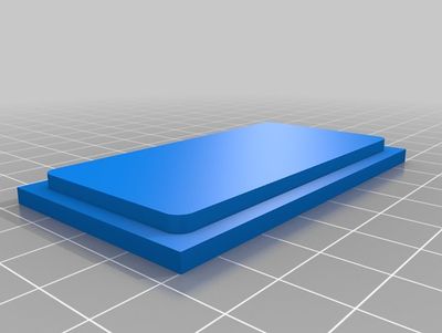
- the 3d-printable decora cover: at thingiverse
- Dimensions:
- Device 6.66 x 3.30 cm
- Hole in trim plate 6.68 x 3.32 cm
- 2 mm ( 0.20 cm) radius on the corners.
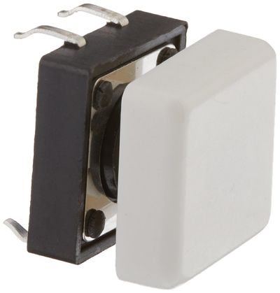
- Buttons are at amazon.
Design questions
How many buttons to control?
- ESCAPE/BACK
- UP
- DOWN
- SELECT/ENTER
- recessed reset button
?
Design Rev. 3.0
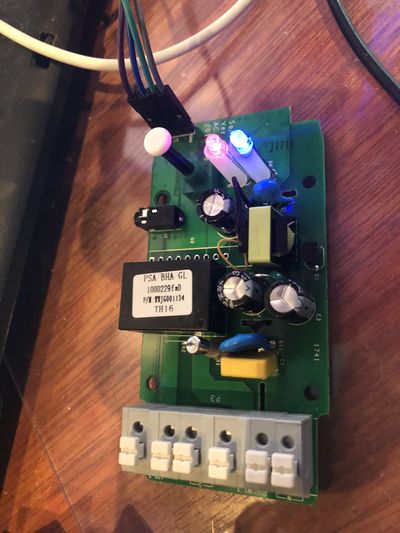
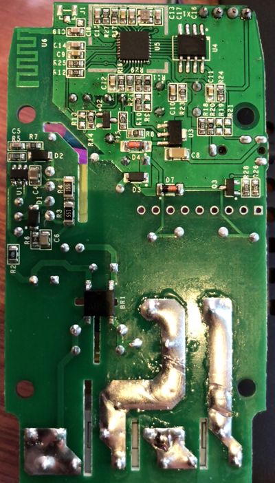
- Use Sonoff 16TH, install firmware found at this link
- before this works, need to have emergency/offline action when network not available, otherwise nothing will shut the fireplace down if network is unavailable
- Schematic here: File:Sonoff_TH10A(16A)_schmatic.pdf
- Find 5V connection for USB power supply on the board
- make sure relay works
- Enclosure:
- Either drill blank Decoray cover and 3d print a mount
- Or 3d print the whole Decora cover including mount
